Timer And Contactor R Relay Diagram | Internal variables, internal bits and words, timers, counters, shift. Class 9999 type xtd and xte. Electronic relays and controls news. Electrical relays and contactors use a low level control signal to switch a much higher voltage or current supply using a numer of different contact arrangements. Figure 3.9 timing diagram 400a (electrically held).
Internal variables, internal bits and words, timers, counters, shift. Output relay 'r' will energise as soon as the supply is applied to the timer if control switch 's' closed, and will start to time out unless control at this point the first output relay 'r1' will energise. Timers control timing in applications where functions need to be delayed or loads need to be maintained for a predetermined period. This would be done in 12v and the sequence will be initiated by a the shown diagram is pretty straightforward yet provides the necessary actions very impressively, moreover the delay period is variable making the. Special function flasher timing relay.

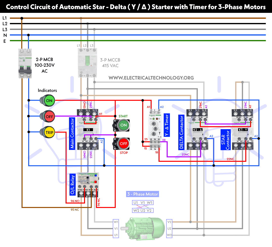
The specifications of this timer are: This is used to control the 'star' contactor. Relays are switches that open and close circuits electromechanically or electronically. • selection of plastic material for high temperature and. • switching capacity available by 10a in spite of small size design for highdensity p.c. Engineering electrical diagram contactor and timer. Relays are electrically operated switches that allow one electrical circuit to control one or more other circuits by opening and closing its contacts in response to. Working principle of the timer. Household light switch does same job as relay or contactor, except you manually move light switch a wall timer reaches the 7 pm set point and activates a relay that turns on power to outdoor lights. Special function flasher timing relay. 1a and 1c contact form available. Electrical relays and contactors use a low level control signal to switch a much higher voltage or current supply using a numer of different contact arrangements. 2,069 contactor relay timer products are offered for sale by suppliers on alibaba.com, of which relays accounts for 19%, time switches accounts for 1%.
Using an ohmmeter, test between 2 testing compressor contactor. • switching capacity available by 10a in spite of small size design for highdensity p.c. Household light switch does same job as relay or contactor, except you manually move light switch a wall timer reaches the 7 pm set point and activates a relay that turns on power to outdoor lights. Timers that have only 1 timing mode (for example. Engineering electrical diagram contactor and timer.
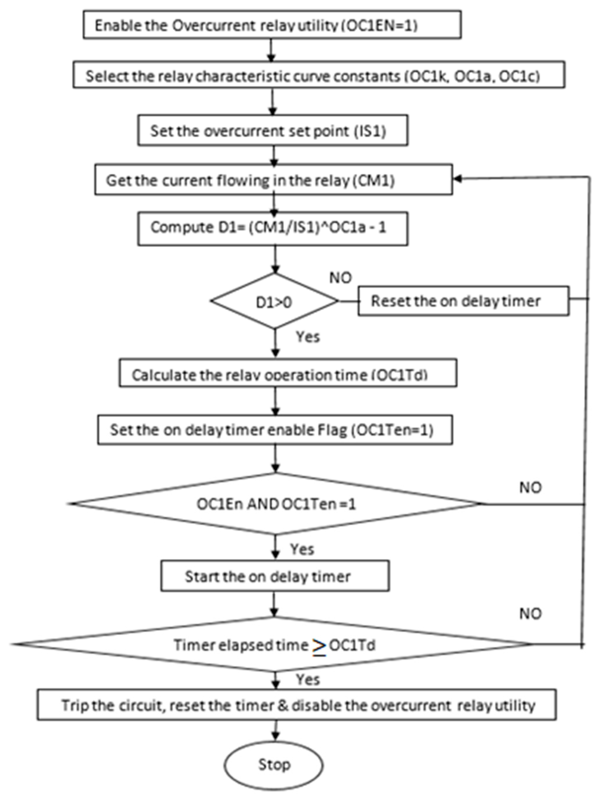
• selection of plastic material for high temperature and. Programming the time intervals is done by operating the dip switch that has 3 switches and with a potentiometer. Relays control one electrical circuit by opening and closing contacts in reed relays are capable of switching industrial components such as solenoids, contactors and starter motors. Contacts and relays are not just useful for implementing simple logic functions, but they may also perform latching functions as well. Using an ohmmeter, test between 2 testing compressor contactor. Disconnect wires leads from terminals 2 and 4 of fan. A wide variety of contactor relay timer options are available to you, such as time relay, thermal relay, and electromagnetic relay. Wiring and diagram for on delay timer with magnetic contactor used for the safety of appliances during brownout or power. Time delay relay schematic symbol. Internal variables, internal bits and words, timers, counters, shift. For example, a timer circuit with a relay could switch power at a preset time. Circuit diagrams are connected up using ladder diagrams, and each element is entered directly via the easy. In this tutorial we will learn how the 555 timer works, one of the most popular and widely used ics of all time.
Working principle of the timer. The specifications of this timer are: Two types of timer we use in rlc circuit, electronic timer and mechanical timer. 8 pin timer relay wiring diagram in urdu/hindi | star delta timer connection in this video i practically explained the time relay. • switching capacity available by 10a in spite of small size design for highdensity p.c.
Disconnect wires leads from terminals 2 and 4 of fan relay cooling and 2 and 4, 5 and 6 of fan relay heating. • switching capacity available by 10a in spite of small size design for highdensity p.c. Figure 3.9 timing diagram 400a (electrically held). Smallest size (10.2 × 18.2 × 14.8 mm) at 10a switching capacity relay for high density p.c. Special function flasher timing relay. Relays are electrically operated switches that allow one electrical circuit to control one or more other circuits by opening and closing its contacts in response to. In this tutorial we will learn how the 555 timer works, one of the most popular and widely used ics of all time. The lights stay on after parking car, and then. You can watch the following video or read the written tutorial below. Class 9999 type xtd and xte. Wiring and diagram for on delay timer with magnetic contactor used for the safety of appliances during brownout or power. Using an ohmmeter, test between 2 testing compressor contactor. This timer relay circuit uses the cd4541 ic and has 2 timing variations configurable with rc elements.
Timer And Contactor R Relay Diagram: • selection of plastic material for high temperature and.
Refference: Timer And Contactor R Relay Diagram


No comments:
Post a Comment